Instructions for the Voltmeter w/Internal Relay
(3 wires coming out of back of meter)
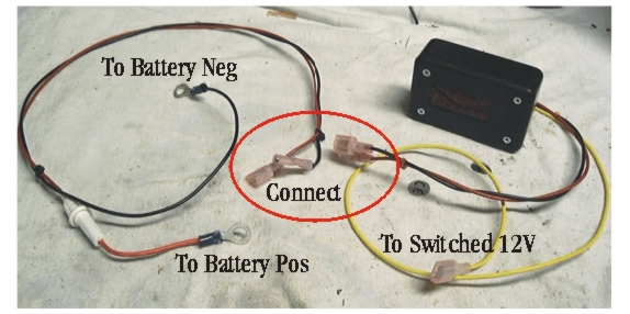
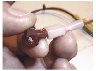
The t-tap included with the meter is used to connect the Yellow wire to a switched wire to turn the meter on and off automatically with the ignition. I've used the brown wire shown at the left (please note, the t-tap in the picture is blue and the one you received with the meter may be red) but just about any other small gauge (14 gauge or smaller) switched wire will do.
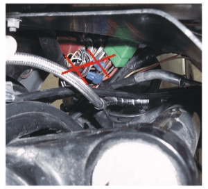
NOTE! Even though the brown wire is suppose to be switched on and off with the ignition, I have had reports that in one case it was always on and in another it never came on. So, you may want to check it before using it.
Please confirm that the meter switches on and off properly before reinstalling any removed bodywork.
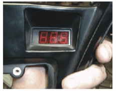
The Digital voltmeter reads up to 20 volts DC and has a resolution of .1 volt. There is actually a .01 volt digit in the meter but I cover it up when I make them because that digit would be jumping all over the place as the bike is running and would be a distraction. I adjust the meters when I build them to within a few hundredths of a volt to my DMM so the accuracy is quite good. The meter has two leads. The Red lead is connected to the positive side of the system and in that lead is a fuseholder with a 1 amp fuse. I dont suspect that the fuse will ever blow but it put there to protect the wiring from a meltdown and a possible fire in the event that the meter would short out. The Black lead is connected to the negative side of the system. Please make sure you are connecting the leads correctly as the meter will not work if you reverse them.
The front faceplate of the meter, the wire entrance and the 4 holes on the back of the meter have been waterproofed but if you want to make it completely waterproof you can do so by backing out the 4 screws on the front face about 1/4 and running a small bead of silicone in the gap between the faceplate and the housing. Retighten the screws (be careful, the case is plastic and you can crack the screw bosses inside if you overtighten the screws) and then wipe of the excess silicone with a rag or trim off the excess after it sets up. That should make the meter fairly well waterproof. I wouldnt let it stand in water but it should survive water spray and rain without incident. If mounting the meter behind the dash panel, there is no need to go through the waterproofing step.
If you are using the supplied brackets to mount the meter behind the dash panel those instructions are near the bottom of this page. If mounting the meter elsewhere, you can use the 4 holes drilled in the back of the meter for attachment. NOTE! Use self-tapping (sheetmetal or wood) screws NO larger than #6 and Do Not let the screws penetrate into the back of the meter more than 3/8. Any futher and the screws may contact the PC board and cause a short. If you have any questions, please dont hesitate to call or e-mail me. 620-241-1515 adnet@mpks.net
1) Remove the dash panel. This entails the removal of numerous things like the windshield, false tank, steering head cover and the like. I recommend that you have the dash panel sitting on the bench but its not absolutely necessary.
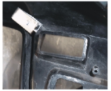
2) Remove the blank plastic cover over the left-hand opening. Save the screws, you will reuse them.
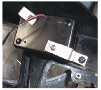
4) Attach the remaining bracket (legs bent in opposite directions to the back of the meter with one of the included screws to the right-lower hole drilled into the back of the meter. Use one of the included lock washers between the screwhead and the bracket. Leave the screw slightly loose.
NOTE! You can determine the top and bottom of the meter by looking at the decimal point on the face of the meter. The decimal point is on the bottom. Also, your meter will probably have the wires coming out of the bottom of the meter unlike the picture shown here.
5) Slide the meter behind the leg of the left bracket installed in step 3 and attach it to that bracket with the remaining included screw and lock washer. Leave the screw a little loose. Attach the right bracket to the dash panel with the other blank-plate screw and just snug it.
6) Looking at the front of the dash panel, adjust the position of the meter in the hole until it is aligned and tighten the screws securely. BE CAREFUL! The screws are threaded into plastic and can strip if tightened too tight.
7) When reinstalling the dash panel, plug the meter in and test it for operation before installing all of the screws and removed bodywork.